Cone Crusher Hydraulic Systems: Adjustment & Sourcing Manual
Engineering guide to troubleshooting cone crusher hydraulic locking loops, calibrating closed-side settings (CSS), and balancing nitrogen accumulator pressure.
Metrological Overview & Hydraulic Force Dynamics
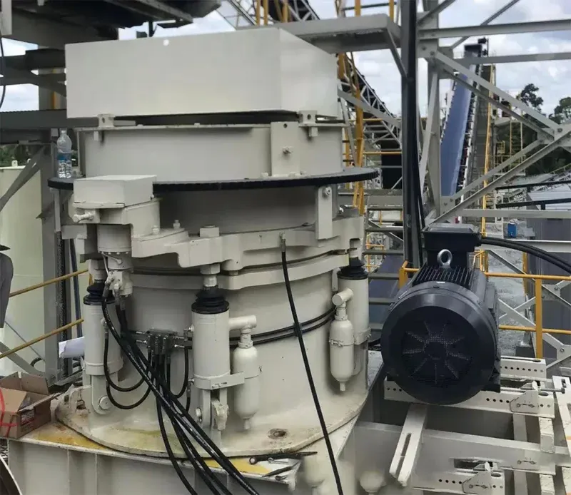
In heavy-duty aggregate processing and hard-rock mining comminution circuits, the mechanical performance of a cone crusher is heavily governed by its integrated hydraulic power pack control network. Modern hydraulic cone crushers leverage specialized fluid power loops to execute two critical operational functions: maintaining the rigid hydraulic locking pressure required to hold the bowl assembly stable during intense crushing cycles, and driving the hydraulic motor ring adjustments that dictate the precise Closed-Side Setting (CSS).
Because the crushing cavity routinely encounters uncrushable tramp iron or dynamic material overloads, the hydraulic loop also serves as the plant's primary defensive line. It must absorb instantaneous mechanical shocks and automatically execute a tramp relief stroke.
If the hydraulic pressure drifts, or if the nitrogen gas accumulators lose their charge, the entire bowl assembly will experience mechanical displacement. This results in direct product sizing degradation, severe thread damage to adjustment rings, and catastrophic structural failure of the main frame.
This technical operation manual provides field service engineers, automation technicians, and plant procurement managers with exact fluid tolerances, nitrogen charging specs, and a structured troubleshooting checklist to permanently stabilize cone crusher hydraulic networks.
The 3 Critical Failure Modes of Crusher Hydraulics
To isolate faults swiftly during an unexpected quarry shutdown, field mechanics must categorize hydraulic system errors into three independent structural loops.
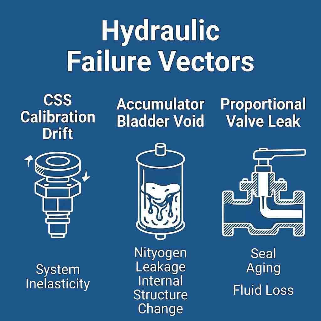
1. Closed-Side Setting (CSS) Calibration Drift (Clamping Failure)
The Closed-Side Setting (CSS) dictates the exact physical gap between the mantle and the bowl liner at its tightest compression point.
- The Slippage Mechanism: During continuous choke-feeding with high-abrasion basalt or granite, the vertical upward forces generated inside the crushing cavity try to force the adjustment ring to rotate upward. If the hydraulic clamping cylinders experience internal pressure degradation (sinking beneath factory design boundaries), the hydraulic lock breaks. The adjustment ring will experience microscopic counter-rotation slips, causing the CSS to drift wider and producing oversized, out-of-spec aggregate.
2. Accumulator Nitrogen Volatilization (Loss of System Elasticity)
Serrated tramp relief cylinders are connected inline to a bank of high-pressure hydraulic accumulators pre-charged with pure Nitrogen ($N_2$) gas.
- The Bladder Void Trap: Over continuous cyclic pounding, nitrogen gas molecules naturally permeate through the internal rubber bladder membranes, dropping the gas pre-charge pressure. When a piece of tramp iron (such as a broken excavator bucket tooth) falls into the crusher cavity, the hydraulic oil has no compressible gas buffer left to displace into. The system suffers an instantaneous hydraulic lock, resulting in cracked main frames or bent main shafts.
3. Directional Proportional Valve Fluid By-Pass (Internal Leaks)
The automated adjustment loop relies on high-precision directional proportional spool valves to route fluid to the hydraulic adjustment motors.
- The Seal Decay Cycle: Fine airborne stone dust and microscopic metallurgic wear debris easily bypass basic tank breathers and score the highly polished surfaces of the valve spools. This internal scoring creates a continuous fluid by-pass pathway. Even when the PLC automation desk indicates that all control valves are locked closed, hydraulic fluid silently seeps back to the reservoir tank, causing the bowl clamping cylinders to creep out of alignment.
Technical Specifications & Hydraulic Pressure Tolerances
The metrological fluid specification matrix below outlines the strict physical parameters and pressure limits required to maintain optimal hydraulic cone crusher tracking.
| Operational Parameter / Node | Target Engineering Boundary | Emergency Failure / Fault Threshold | Specialized Measurement Device |
|---|---|---|---|
| Bowl Clamping Line Pressure | 14.0 MPa to 18.0 MPa (140-180 bar) | < 11.5 MPa (Imminent Clamping Slip) | Glycerin-Damped Pressure Gauge |
| Tramp Relief System Pressure | 18.5 MPa to 22.0 MPa (185-220 bar) | > 25.0 MPa (Relief Valve Blow-off) | High-Pressure Inline Transducer |
| Accumulator $N_2$ Gas Pre-Charge | 7.0 MPa to 9.0 MPa (70-90 bar) | < 5.0 MPa (Total Shock Elasticity Loss) | Gas Charging Kit with Tester |
| Hydraulic Fluid Cleanliness | ISO 16/13/11 Standard (Strict) | > ISO 20/17/14 (Rapid Valve Scoring) | Laser Particle Fluid Counter |
| Proportional Valve DC Voltage | 0V to 10V DC / 4-20mA Stable Loop | Loop Disconnection (Signal Fault) | Digital True-RMS Multimeter |
Step-by-Step CSS Adjustment & Hydraulic Calibration Sequence
When the automated SCADA monitor registers an out-of-spec material sample or a low clamping pressure alarm, maintenance crews must execute this structured fluid calibration sequence immediately.
Step 1: Execute Complete Mechanical Isolation & Zero Leak Verification
- Isolate the main crusher drive motor using rigid Lockout-Tagout (LOTO) safety protocols. Keep the independent hydraulic power pack running during initial testing.
- Inspect every external hydraulic hose, dual-acting cylinder packing gland, and manifold junction block for visible weeping or fluid pooling.
- Clean the position-indicator sensors mounted on the adjustment ring. Ensure the automated distance tracking lasers or inductive proximity switches are free of grease-sand crust, which can distort electronic CSS calibration feedback loops.
Step 2: Test and Recharge the Nitrogen Accumulator Bank
If the crusher operates with an aggressive, jarring metallic thud every time an uncrushable particle enters the cavity, the accumulators are dead:
- Depressurize the hydraulic fluid side of the tramp relief circuit entirely by opening the manual bleed valve on the power pack manifold.
- Unscrew the safety protective cap from the top gas valve of the accumulator.
- Attach a dedicated nitrogen gas charging manifold assembly complete with an accurate analog test gauge.
- Read the static gas pressure. If the ambient temperature is 25°C and the gauge reads below 6.0 MPa, connect a high-pressure commercial Nitrogen gas cylinder to the charging kit.
- Slowly crack the regulator to charge the internal bladder until the pressure settles precisely at 8.0 MPa (80 bar). Engineering Safety Rule: Never use compressed oxygen or standard shop air to charge a hydraulic accumulator; mixing compressed oxygen with petroleum-based hydraulic oil triggers an immediate, catastrophic diesel-effect internal explosion.
Step 3: Calibrate the Closed-Side Setting (CSS) via the Lead-Wire Test
To ensure your digital PLC display matches the physical realities inside the crushing chamber, execute a physical lead-wire calibration verification check:
- Obtain a solid core lead-wire strand with a diameter roughly 5mm larger than your target CSS (e.g., use a 20mm lead wire if targeting a 15mm setting).
- Attach the lead wire to a flexible nylon rod. With the crusher running completely empty at full operational RPM, drop the lead wire vertically down into the side crushing cavity until it passes completely through the tightest sizing parallel zone at the bottom, then pull it back out.
- Use a digital micrometer caliper to measure the exact thickness profile of the crushed, flattened section of the lead wire.
- Compare this physical measurement with the numeric readout displayed on the SCADA screen. If the screen registers
12mmbut the lead wire measures14.5mm, navigate to the Automation Sensor Calibration Override Screen, input the physical14.5mmbaseline value, and press calibrate to update the PLC's internal linear displacement coefficients.
[ Depressurize Oil Loop ] ──> [ Connect N2 Gas Tester ] ──> [ Charge Bladder to 8.0 MPa ] ──> [ Lock Clamping Cylinders ]
Step 3: Calibrate the Closed-Side Setting (CSS) via the Lead-Wire Test
To ensure your digital PLC display matches the physical realities inside the crushing chamber, execute a physical lead-wire calibration verification check:
- Obtain a solid core lead-wire strand with a diameter roughly 5mm larger than your target CSS (e.g., use a 20mm lead wire if targeting a 15mm setting).
- Attach the lead wire to a flexible nylon rod. With the crusher running completely empty at full operational RPM, drop the lead wire vertically down into the side crushing cavity until it passes completely through the tightest sizing parallel zone at the bottom, then pull it back out.
- Use a digital micrometer caliper to measure the exact thickness profile of the crushed, flattened section of the lead wire.
- Compare this physical measurement with the numeric readout displayed on the SCADA screen. If the screen registers
12mmbut the lead wire measures14.5mm, navigate to the Automation Sensor Calibration Override Screen, input the physical14.5mmbaseline value, and press calibrate to update the PLC's internal linear displacement coefficients.
Advanced Sourcing & Procurement FAQ
Q1: What factors dictate whether a procurement team should source an accumulator system utilizing top-repairable or bottom-repairable shell configurations?
A1: For high-uptime aggregate and mining circuits, procurement teams should strictly mandate top-repairable accumulator shells. Top-repairable configurations allow maintenance mechanics to unbolt the gas valve assembly, extract a ruptured rubber bladder, and install a brand-new OEM seal kit straight through the top of the unit while it remains fully bolted to the heavy hydraulic manifold rack. Bottom-repairable models require the entire high-pressure steel shell to be unbolted from the fluid piping lines, increasing repair downtime from 1 hour to over 5 hours.
Q2: How does specifying a variable-displacement piston pump instead of a standard gear pump affect the long-term lifecycle cost of a crusher hydraulic power pack?
A2: Specifying an automated variable-displacement axial piston pump with pressure-compensation controls significantly optimizes long-term lifecycle costs. Standard gear pumps continuously push maximum oil volumes at high pressures, forcing excess oil to continuously bypass through relief valves back to the tank, which generates extreme heat and rapidly degrades fluid additives. A pressure-compensated piston pump automatically de-strokes and drops its volumetric flow rate to near zero once the main bowl clamping cylinders hit their 16 MPa locking threshold, cutting power pack electrical consumption by up to 60% and doubling fluid life.
TAG
cone crusher hydraulic adjustments manual,how to adjust cone crusher closed side setting,cone crusher hydraulic power pack troubleshooting,cone crusher accumulator nitrogen charging
Request Technical Blueprints & Factory Quotes
Submit your machinery parameters below. Connect directly with verified, certified heavy industrial manufacturers to receive custom foundation drawings, layout schematics, and direct-from-factory pricing.